|
I was fortunate enough to have my electricity meter changed to the new digital type with a liquid crystal display. One of the interesting features of this meter is that it has a very bright LED which flashes once every 1/1000 Kwh used. This got me thinking about building an interface to pick up the flashes via a sensor and feeding this into my one-wire network.  I happened to be in my local Maplin's (UK electronics store) and found that they sold Infra-red barrier mini-kits from Velleman (MK120). Info here and here. This consisted of a transmitter and receiver PCB complete with components. Being under ten pounds, I purchased this kit to see if it would suit my needs. To my amazement, with a very minor modification, this was the perfect first interface for the project. The receiver side of this kit consists of a photo diode which is designed to pick up infra-red from the transmitter. Looking at the transmitter circuit diagram (Receiver diagram also here ), the transmitter LED's were actually being fed from a astable oscillator. The modulated IR Light was then being received by the photo diode on the receiver pcb and fed into various op amp stages to integrate and compare the voltages obtained. This voltage (when the photo diode received IR light) was compared to a reference voltage and would switch the final opto to an OFF state. This would then switch to an ON state when no IR illumination was received. For its intended application, the buzzer & LED would activate when somebody crossed the beam. I really needed the output to be the reverse of this so I decided to modify the receiver pcb by swapping the + and - inputs of the last comparator. This involved 4 cuts on the PCB and a few bits of wire to transpose the connections. I was going to use the final output transistor as the switch for the 1-wire but thought it would be nice to leave the LED as an indicator. Instead, I used a spare BC547 transistor & 1K resistor (from the transmitter) as the switch interface. The buzzer was never installed on the PCB. The 1-wire interface was the easy bit. One of the common uses for this bus is for temperature and weather related devices. Several weather instruments require counters to input the data and this includes rain gauges & lightning detectors. A company called AAG in Mexico manufacture 1-wire counter boards (TAI8585) at minimal cost. These consist of a battery backed DS2423 counter (so no counts are lost) which can be triggered by a reed relay or other shorting method. This seemed ideal and I purchased one for this project. Info here. These two boards then made up the main interface and the 1-wire output fed into my Midon Design TEMP08 and then to the Homeseer PC via a serial interface. Construction One of the most important parts of this project was how to mount the photo diode in front of the pulsed LED without obstructing the meter too much and raised eyebrows from the meter reader. A 8mm wide length of sheet metal was bent in to a Z formation with a 5.5mm hole drilled at the end and another 4mm for mounting. This was then sprayed white. 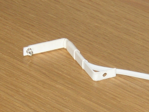 In the original design, I used telephone cable to solder onto the photo diode but due to interference from mains spikes being picked up in the cable, this was later changed to screened cable.  The Velleman receiver kit was constructed apart from the photo diode and the buzzer. R11 was replaced from a 470K to 15K to reduce the sensitivity of the circuit. As mentioned before, I needed to swap pins 9 and 10 on the LM324 IC. As the pads on the PCB could get dislodged, cutting of the board was done after construction with a sharp knife. A meter set to low resistance was then used to confirm that the tracks had been completely cut. Wire links as shown were then added to complete the modification.  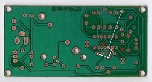 Connection of the photo transistor and 9V battery to the circuit confirmed correct operation with the on-board LED flashing at the same time as the meter LED. I found out by chance that the AAG 1-wire counter could be mounted on top of the Velleman PCB using the mounting holes designed for the battery holder. Two 25mm M3 pan head screws were used to mount the AAG board. I needed to add a small transistor and resistor to allow the one-wire counter to be triggered from the Velleman board. A 1K resistor with sleeving was soldered to R12 and pushed through the large hole nearby so that it appeared at the top of board. The collector and emitter of the BC547 were then soldered directly to the 1-wire board (across the reed relay) and the other end of the 1K resistor soldered to the base of the transistor. Finally a ground/common wire was connected from the Velleman PCB to the 1-wire PCB. 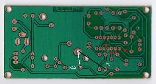  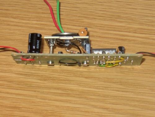 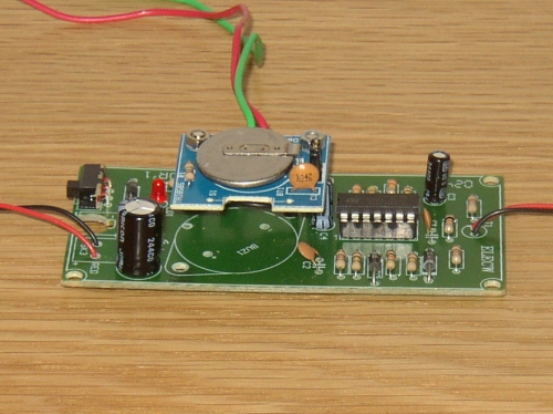 All that was needed was to mount the finished interface within a plastic box. I added two sockets - one for the photo transistor and the other for the 1-wire & 12V supply. In addition, I de-soldered the LED and also mounted this on the side of the box. The 12V supply was obtained from the TEMP08. 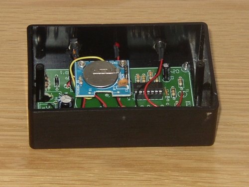 Problems I originally had an issue with the circuit being too sensitive and extra pulses were detected when switching on the kitchen fluorescent lights. This was totally eliminated by reducing the sensitivity of the circuit by replacing R11 on the Velleman PCB from 470K to 15K. In addition, using screened cable on the photo-transistor also helped. I would recommend keeping the sensor cable length as short as possible. One other issue that I did not foresee was that the TEMP08 counter only goes to 65535 (FFFF) before it resets to zero. As the meter pulses 1000 times every Kwh, this can add up very quickly. The only way to get raw counter value from the DS2423 was by using the TEMP08 in debug mode. This was giving out far too much data and was discounted. I now use Homeseer scripting to store an incremental counter value in a ini file and adjust the count automatically even when the counter resets to zero. This is updated every minute. Two logging files are produced. One is the data recorded for the day and is created every day automatically. The second is a 2 day log (today & yesterday). This is used to generate the logging data for the web server (last hour & last 24 hours). One of the things this project has highlighted is how much my home costs to run. Even during the night, I am using over 1KWh to supply computers, interfaces, fridge & freezer etc and all those other gadgets which glow on standby! If you try this yourself, please let me know how you got on. Data display Basic monitoring graphs for the last hour and 24 hours can be seen on my home automation server. This is what you will see: 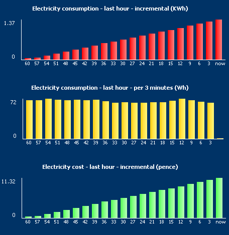 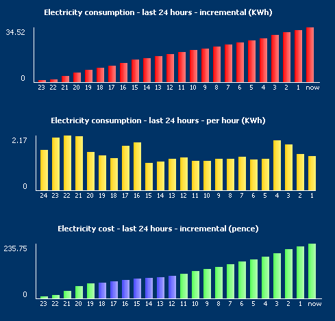 The circuit has now been tried and tested by another 1-wire user in the Netherlands. Take a look at his site here. |